Data Communications

How to Ensure MPO/MTP Systems Work with Correct Polarity?

With the appearance and development of 40/100G Ethernet network, MPO/MTP technology is developed for migrating to 40/100GbE, which is of high density, flexibility and reliability with scalable, upgradeable properties. Do you want to upgrade your system to 40/100G Ethernet network? Are you familiar with MPO/MTP technology? Do you know how to ensure MPO/MTP systems work with correct polarity and why the polarity of the connections using multi-fiber MPO/MTP components from end-to-end should be assured?

Generally, MPO/MTP technology is to pull just one single cable with multiple fibers, which is deployed for multi-fiber applications. When using the technology in 40/100G Ethernet network, only maintaining a correct polarity across the fiber network, could you ensure that the signal transmitted from any of the active equipment can be directed to the receive port of the next active equipment. In order to ensure MPO/MTP systems work with correct polarity, experts develop three methods that will be presented in this paper.

Three Polarization Methods with Corresponding MPO/MTP Cables

For ensuring proper polarity, experts put forward three polarization methods, which are defined by TIA 568 standard and named as Method A, Method B and Method C. As different polarization methods employ different MPO/MTP trunk cables to connect the fiber network, there are three types of MPO/MTP truck cables with different structures called Type A, Type B and Type C used for the three different connectivity methods respectively. The following will introduce the detailed information of each method with its corresponding truck cable.

Polarization Method A with Type A Trunk Cable

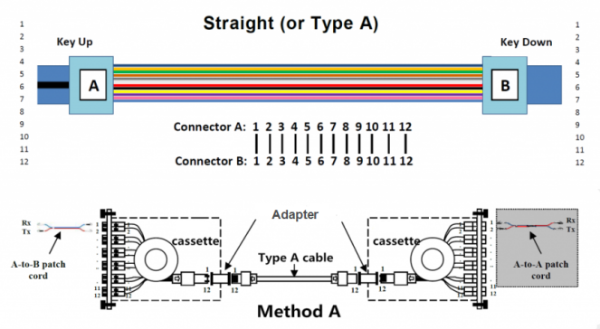
To better understand Polarization Method A, the Type A Trunk Cable should be first introduced that is also referred to as straight cable. It is a straight through cable with a key up MPO/MTP connector on one end and a key down MPO/MTP connector on the opposite end, which makes the fibers at each end of the cable have the same fiber position as shown in the following figure. For instance, the fiber located at position 1 (P1) of the connector on one side will arrive at P1 of the other connector, and the fiber located at P12 on one side will arrive at P12 on the other side.

As for Polarization Method A, it always works with the Type A trunk cable that is designed to connects MPO/MTP modules on each side of the link. The connectivity Method A is also shown in the following figure for your reference.

photo20161104a

Polarization Method B with Type B Trunk Cable

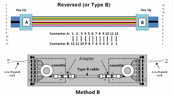
In Polarization Method B, Type B truck cable is used to connect the two modules on each side of the link. Clearly different from Type A trunk cable, Type B trunk cable uses two key up connectors on both ends of the cable, which is known as reversed cable. This mating structure results in an inversion, which means the fiber positions are reversed at each end. For example, the fiber at P1 of one end is mated with the fiber at P12 of the opposing end. From the following figure, you can learn the fiber sequences of a 12 fiber Type B cable and the connectivity Method B.

photo20161104b

Polarization Method C with Type C Trunk Cable

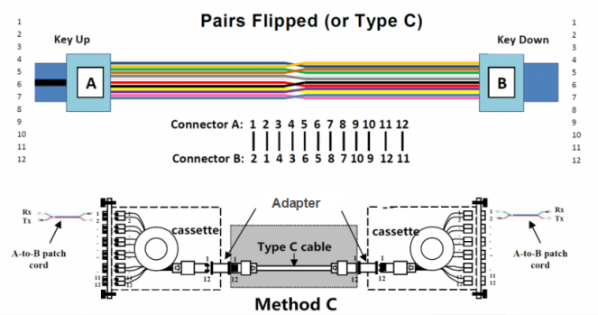
Compared with the previous methods, Polarization Method C is more complicated that works with Type C trunk cable. Type C trunk cable is used for connecting MPO/MTP modules one each side of the link which can be also called pair-reversed trunk cable. You can study the connectivity Method C in the following figure.

Just like Type A trunk cable, Type C trunk cable also has one key up connector and one key down connector on each side. However, it is more sophisticated because each adjacent pair of fibers are designed to flip at each end. That’s to say, the fiber at P1 on one end of the cable will be shifted to P2 on the other end and the fiber at P2 on one end will be mated with P1 on the opposite end, etc. To help you better understand the fiber sequence of Type C cable, you can take the following figure as reference.

photo20161104c

Conclusion

From this paper, we can conclude that there are three polarization methods which are developed to ensure MPO/MTP systems work with correct polarity, and each polarization method has its own trunk cable to connect the modules in each end of the link. If you want to upgrade your system to 40/100G Ethernet network, you can choose the most suitable method for assuring the correct polarity in your fiber network, which will make your system work great.

Fiber Optic Patch Cable

MPO/MTP Solution for High-Density Data Centers

With the rapid development and prevalence of cloud computing and big data, the requirements for transmission speed and data capacity become much higher than ever before, which makes 40/100G Ethernet be an inevitable trend for data center cabling system. However, as science and technology develop day by day, new questions are always following soon and waiting for the right solutions. For the coming and progress of 40/100G Ethernet network, the traditional LC cabling is too complicated to meet the demands for high density in data centers. Thus, making the traditional LC cabling less complicated or designing a brand new kind of cabling to replace the previous one becomes an imminent issue.

How to solve the issue so that the time and space spent on cable installation would not be wasted? MPO/MTP cabling solution turns out to be the right method for high-density, easy plug and play connection in complicated cabling infrastructure.

What’s MPO/MTP?

MPO/MTP is a technology deployed for multi-fiber applications, which aims at pulling just one single cable with multiple fibers. The word MPO stands for “Multiple-Fiber Push-On/Pull-off”. Through MPO/MTP technology, you can replace 12 or 24 LC connectors with only one MPO/MTP connector. In other words, you only need to patch one cable with multiple fibers, instead of patching 12 or 24 separate fiber cables.

Generally, MPO/MTP technology is a high-density, high-performance solution, widely used for 40/100G Ethernet network as well as fast installation of enterprise data center. With the advantage of MPO/MTP fiber systems, a much higher bandwidth transmission in data communication is no longer a dream.

MPO/MTP Fiber Optic Jumper Cable

MTP/MPO fiber optic jumper cable consists of MTP/MPO cable and MTP/MPO connectors, which is designed for the reliable and quick operations in data centers. With its advantages of less space and scalability improvement, significant space and cost savings are provided to user. What should be noted is that MTP cable is upgrade version of the former MPO, with better optical and mechanical performance. As for the connectors, both MTP and MPO connectors are multi fiber connectors, each of which has many fiber optic channels. Since MPO/MTP connectors are the up-and-coming standard optical interface for 40/100G Ethernet network, there is no doubt that MPO/MTP fiber optic jumper cable will eventually flood the data center. After all, the high fiber count in one connector creates endless possibilities.

photo1.png

Advantages of MPO/MTP Products

Compared with traditional fiber products, there are many improvements in MPO/MTP Products, such as, faster and easier installation, lower cost and higher density with less space. The following will introduce the detailed information for MPO/MTP products’ advantages.

As we know, in contrast to traditional fiber cabling, MPO/MTP cabling is much easier and faster. It is estimated that the installation time of MPO/MTP cabling can be reduced by up to 75% for MPO/MTP products’ simple push-pull latching mechanism. The installation method of MPO/MTP products is just pulling and plugging, which is designed to easy and intuitive insertion and removal. Hence, all unpredictable field termination troubles can be eliminated, while the installation time involving a costly high-qualified workforce can be reduced to a minimum.

High density is another feature of MPO/MTP products. For their multi-fiber structure, there are 12/24 fibers in only one cable running at the same time, providing 12/24 times the density, which facilitates high density communication. Beside, most MPO/MTP products belong to modular solutions, which could be a good choice to ease future expansion and for quick and easy system reconfiguration.

Conclusion

With the improvement of network technology, 40/100G Ethernet seems to be a prevalent trend. To meet the growing demands of fiber optic market, MPO/MTP products are developed and largely used in a really fast manner, dramatically providing the ideal solution for high density cabling data center.