CWDM Network

Analysis of Power Budget and Link Distance in CWDM System

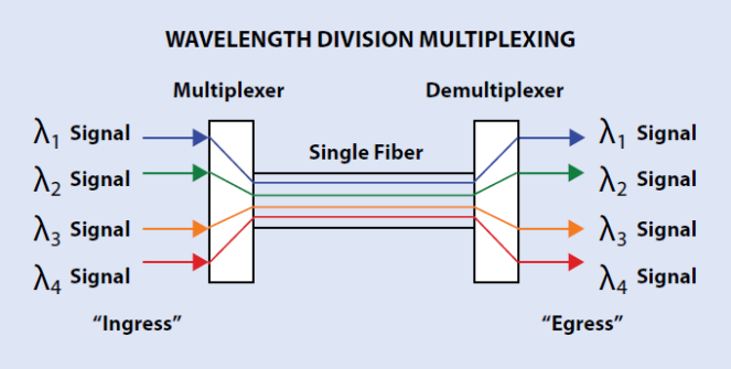
It can’t be denied that CWDM technology is a cost effective method to increase the capacity in the existing system, which can give different wavelengths to multiple optical signals and multiplex them for transmission through only one single fiber. Different from the DWDM system, the network using CWDM technology are deployed by passive components like passive CWDM Mux Demux, without the need of additional power, which makes CWDM system more commonly used. Do you also plan to build a CWDM system? If yes, you can check the following information for reference, which mainly analyzes the optical power budget in a CWDM system and calculates the CWDM link distance according to the power budget for smoothly deploying a CWDM system.

What’s Optical Power Budget?

Before deploying an optical network, it is very essential to calculate the optical power budget for better deployment. What’s optical power budget? It is just the amount of light available to make a successful fiber connection which can be calculated by analyzing the original output power of the transmitter and the required input power of the receiver. In details, we should firstly learn the optical power that is emitted by the source (also referred to Transmit Power) and the required power of the detector (also called Receiver Sensitivity). Using the first data to subtract the second one, you’ll get the data of the optical power budget which greatly determines the performance of the whole network link.

Here is the equation: Optical Power Budget = Transmit Power – Receiver Sensitivity.

How to Get the Optical Power Budget in a CWDM System?

To estimate the link distance supported by a CWDM system, the optical power budget should be calculated first, which can greatly determine the CWDM link distance. Here will show you a basic CWDM system under an ideal condition to clearly illustrate how to get the optical power budget. In this basic CWDM system, there is a optical transmitter which transmit power is -2 dBm and a optical receiver with -25 dBm receiver sensitivity. Hence, the optical power budget is 23 dB, as shown in the following equation.

Optical Power Budget = Tx Power – Rx Sensitivity = -2 dBm – (-25 dBm) = 23 dB

However, the mentioned CWDM system is just under an ideal condition without loss caused by the signal transmission. In a normal CWDM system, there are many components like passive CWDM Mux Demux, CWDM transceiver inserted. All these components cause insertion loss once they are inserted into the CWDM link. Therefore, when doing the optical power budget, all the loss should be taken into account for calculating the power budget exactly.

Here is more exact equation: Power Budget = Tx Power – Rx Sensitivity – Loss

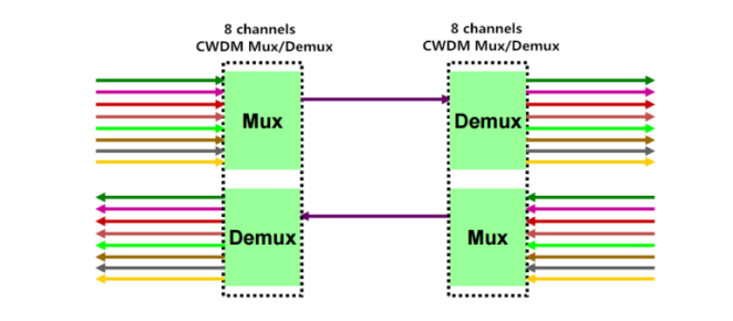
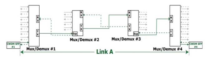
To get the real power budget of a CWDM system, here offers a simple CWDM link which uses the -2 dBm optical transmitter, -25 dBm optical receiver and four passive CWDM Mux Demux with low insertion loss. Both the stable 4 channel CWDM Mux and stable 4 channel CWDM Demux in the link have 2.0 dB insertion loss, and other two are 8 channel ones feature 2.5dB insertion loss separately, as shown in the figure below. As a result, the total loss caused by the four passive CWDM Mux Demux is 9 dB, resulted from 2.5 dB + 2.0 dB+2.5 dB + 2.0 dB. Then we can get the total power budget, 14 dB. The calculation process is: Power Budget = Tx Power – Rx Sensitivity – Loss = -2 dBm – (-25 dBm) – 9 dB = 14 dB

Power Budget for CWDM Network

How to Calculate the Link Distance in the CWDM System?

After knowing the optical power budget, let’s calculate the link distance of the CWDM system according to the following equation: Link Distance = Optical Power Budget/Fiber Attenuation. As there may be some other power loss caused by the factors that we didn’t consider like fiber aging, temperature and poor splice, we often subtract 2 dB buffer from the total optical power budget. Meanwhile, the fiber attenuation is changeable according to the wavelength, usually varying from 0.2 to 0.35 dB/km. In this case, we’ll use 0.35 dB/km as a typical data. Then we can get the link distance is about 34 km. The calculation process is Link Distance = Optical Power Budget/Fiber Attenuation = (14 dB- 2 dB)/0.35 dB/km.

Conclusion

This paper intends to illustrate how to calculate the optical power budget and estimate the link distance of a CWDM system according to the optical power budget, which allows for better budget of deploying the CWDM system and eliminates the unwanted or unnecessary issues which may happen in the system deployment. Besides, if you want to make a cost effective CWDM system, you are suggested to buy CWDM components like cheap passive CWDM Mux Demux, CWDM transceivers from FS.COM, which are of good price and quality.

CWDM Network

Why Not Build a 10G CWDM Network for Higher Capacity?

Although the 40G and 100G technologies develop vigorously recent years to meet the increasing need of higher capacity, they are still not widely accepted and applied due to high deploying cost. Under this case, choosing to build a 10G network is always the first choice for most users. But except upgrading our system, what else can we do when the 10G network can’t offer enough capacity? To address this issue, telcom engineers and researchers suggest that we can deploy the 10G CWDM networks. With use of CWDM optical multiplexer, this solution offers a highly cost effective method to gain more capacity on the basis of 10G network. Let’s study the benefits of 10G CWDM network and its two basic common network infrastructures in details.

What Can We Benefit from 10G CWDM Network?

In contrast to 10G DWDM network, 10G CWDM network can neither offer so high data capacity nor transmit the signals so long. But on the other hand, 10G CWDM network is an easier-to-deploy and less expensive solution that can well serve for a wide range of optical applications. Let’s study the main benefits of 10G CWDM networks.

  • It is possible to add connections for transmitting more data in 10G network, which makes the whole network load increasing from 10G to 40G or 100G possible.
  • CWDM Mux Demux is the key component of 10G CWDM network. As a passive component, it doesn’t require extra power, which is an ideal option for deploying 10G CWDM network.
  • Instead of upgrading system, deploying 10G CWDM network to get more capacity can saves a lot of money due to the economical 10G hardware and cheap passive CWDM Mux Demux.

Understanding Common 10G CWDM Network Infrastructures

10G CWDM system is a passive optical network, which supports 10G transmission with any protocol over the optical link, as long as the 10G signals are at the specific CWDM wavelengths. At present, there are two common CWDM network infrastructures. One is 10G CWDM point-to-point network, and the other is 10G CWDM ring network. The following will introduce the two common infrastructures in details.

10G CWDM Point-to-Point Network: it is the simplest network infrastructure of the CWDM networks. As shown in the following figure, there are two passive CWDM Mux Demux deployed in the 10G network that offers 8 channels to multiplex the signals from 8 different optical fiber link into an integrated signal. Thereby, the signal can be transmit through only one fiber, which means there are 7 virtual fiber created with higher capacity for transmitting more data. As for the cheap passive CWDM Mux Demux, it can be available at very good price that costs less than upgrading the system from 10G to 40G or 100G. Undoubtedly, deploying a 10G CWDM point-to-point network is very economical solution for higher capacity.

10G CWDM Point-to-Point Network with CWDM Mux Demux

10G CWDM Ring Network: it is deployed on the basis of 10G CWDM point-to-point network. Compared to point-to-point network, the ring network is much more complex that needs other optical CWDM components like CWDM OADM. By adding CWDM OADM, two or more point-to-point network can be connected together, which can finally achieve a 10G CWDM ring network. To better understand how does the 10G CWDM ring network work, here offer a figure that shows four buildings are connected by several 8 channels CWDM Mux Demux and CWDM OADM for your reference.

10G CWDM Ring Network with CWDM Mux Demux

Conclusion

Unlike upgrading the network from 10G to 40G or 100G, building a 10G CWDM network doesn’t requires changing all the network equipment which may cost highly. It only need CWDM transceiver and CWDM Mux Demux to be deployed in the original 10G network. For a complex 10G CWDM network, additional optical equipment like CWDM OADM are required. If you come across the capacity-hungry issue, building a 10G CWDM network would be a nice option for higher capacity.

CWDM Network

Single Fiber CWDM Network Overview

When designing the fiber optical network, we used to choose the duplex fiber cable as the first choice to finish the dual-way transmission, which transmits the dual-way signals via two separate simplex cables from the opposite sides. However, in some typical dual-way applications like working with BiDi fiber optic transceiver, the simplex fiber cable is required to transmit the dual-way signals respectively over only one fiber cable by using two different wavelengths that has a more complicated working principle than the duplex one. If we want to deploy a single fiber CWDM network, the basic principle is similar to simplex fiber cable but would be much more complicated, which will be explained detailedly in this post.

What Is the Single Fiber CWDM Network?

Single fiber CWDM network is a special kind of WDM network that can greatly increase the network capacity by combining and transmitting several pairs of signals with different wavelengths over a single fiber, with the aim of supporting several dual-way connections at the same time. To deploy the single fiber CWDM network, a pair of single fiber CWDM multi-channel Mux/Demux and several pairs of CWDM transceivers are needed. When the single fiber CWDM network works, the two single fiber Mux Demux require different wavelengths for each pair of dual-way transmission, which is very different from the dual fiber Mux Demux using the same wavelength for a pair of dual-way transmission. That’s to say, there are only four different wavelengths used for 4-channel dual fiber CWDM Mux Demux, but eight different wavelengths divided into four pairs for 4-channel single fiber CWDM Mux Demux.

How Does the Single Fiber CWDM Network Work?

Before talking about the single fiber CWDM network, let’s take a simple BiDi network as an example first. In the BiDi network, only one simplex fiber cable and a pair of BiDi fiber optic transceivers are required to finish the dual-way connection. In details, the two BiDi fiber optic transceivers should be almost the same but has reversed wavelengths for TX and RX. For instance, if one transceiver with 1490nm for TX and 1310nm for RX is installed in one end of the fiber link, the other one in the opposite end should use 1310nm for TX and 1490nm for RX, as shown in the following figure. Hence, the dual-way signals with two different wavelengths can be transmitted over only one fiber cable.

Dual-way Transmission with BiDi Transceiver and Simplex Fiber Cable

As for the single fiber CWDM network, its basic principle is similar to the BiDi network but would be much more complicated, which can be also learned from the following figure. In the figure, there are two 4-channel single fiber CWDM Mux Demux connected to each ends of the single fiber, and four pairs of CWDM SFP+ transceivers designed with eight different wavelengths, totally achieving the 4-channel single fiber CWDM network. It is easily to learn that these eight different wavelengths are divide into four pairs and each pair has the complete reversed TX and RX. For instance, the first pair of CWDM transceivers consist of a transceiver with 1490nm for TX and 1310nm for RX in the left side and a transceiver with 1490nm for TX and 1310nm for RX in the right side, thereby a pair of dual-way signals with two different wavelengths will be transmitted through the first channel. To better understand how does the single fiber CWDM network work, the following table lists the eight ports with four pairs of wavelengths for TX and RX that are all reversed to ensure the dual-way transmission.

Single Fiber-CWDM Network

Four Pairs of Wavelengths for TX and RX

Conclusion

The single fiber CWDM network can greatly increase the network capacity for transmitting larger dual-way data signals, which is able to combine several pairs of signals with different wavelengths into an integrated signal and carry it through a single fiber. To build a smooth single fiber CWDM network, you should firstly install the CWDM fiber optic transceivers into two switches and then connect them into the channel ports of the two single fiber CWDM Mux Demux, finally use a single-mode simplex fiber cable to link the two CWDM Mux Demux together. Besides, to ensure the performance of the single fiber CWDM network, there are some important factors like light loss, transmission distance, and optical signal dropping and adding should also be taken into consideration.

Fiber Optic Transceiver

Is PSM or CWDM More Cost-effective for 40GBASE-LR4 QSFP+ Optic?

Since 40G Ethernet network becomes much more widely used than ever before to meet the data center needs, there are various 40G optics available in today’s fiber market for different applications. As for short distance application, 40GBASE-SR4 QSFP+ optic has a high performance with the parallel multimode fiber (MMF) link. While for long distance application, 40GBASE-LR4 QSFP+ optic has been put into use that can work with two kinds of links, parallel single-mode fiber (PSM) link and coarse wavelength division multiplexing (CWDM) link. Do you have a good knowledge about the two links? Which one is more cost-effective in 40G long distance transmission? In this paper, it will mainly talk about this topic that may guide you to choose the right link for 40GBASE-LR4 QSFP+ optic.

40GBASE-LR4 QSFP+ Optic with PSM Link

How does the 40GBASE-LR4 QSFP+ optic work with PSM Link? Generally, it is designed to transmit signals through parallel single-mode fiber (SMF) link that can be also called PSM QSFP+ optic. A PSM QSFP+ optic has four independent channels to transmit and receive 10G signal to achieve a total 40G signal transmission at lengths up to 10 km. MTP/MPO fiber ribbon connector is required in this optic to match with the parallel single-mode fiber link, while the guide pins inside the receptacle is also needed to ensure proper alignment. What should be paid attention to is that the single-mode fiber cable cannot be twisted for the sake of channel to channel alignment.

In its working process, the transmitter module of the optic will accept electrical input signals, while the receiver module has the ability to convert parallel optical input signals via a photo detector array into parallel electrical output signals. Both electrical input and output signals are voltage compatible with common mode logic (CML) levels, supporting a data rates up to 10.3G per channel.

40g-psm-qsfp

40GBASE-LR4 QSFP+ Optic with CWDM Link

The 40GBASE-LR4 QSFP+ optic with CWDM link is also known as CWDM QSFP+ optic, which takes full advantages of CWDM technology to achieve 40G transmission. Similar to the PSM QSFP+ optic, it also offers four transmitting and receiving channels, and each of the channel is capable of 10G operation for a total 40G data rate with a reach of up to 10 km through single-mode fiber cable.

However, the working process of CWDM QSFP+ optic is much complicated than the previous one, since the duplex LC connector is implemented to accommodate CWDM technology in this optic as shown in the following figure. In its working process, it will firstly use a driven 4-wavelength distributed feedback (DFB) laser array to convert four 10G electrical inputs signals to four CWDM optical signals with different wavelengths, generally 1271, 1291, 1311 and 1331 nm, and then multiplexes these CWDM signals into a single channel as a 40G signal, propagating out of the transmitter module through the SMF. When these CWDM signals come to the receiver module, they will be de-multiplexed into four individual 10G optical signals and transmitted through each individual channel, which will finally be collected by a discrete photo diode, amplified by a transimpedance amplifier (TIA) and output as electric signals.

40g-cwdm-qsfp

Which One Is More Cost-effective?

As we know, 40GBASE-LR4 QSFP+ optic can work with either CWDM link or PSM link, supporting 40G Ethernet network at lengths up to 10 km. Then, which one is more cost-effective? If we only consider the QSFP+ optic cost, it is apparent that the PSM QSFP+ optic is more cost-effective with a single uncooled CW laser and relatively simple array-fiber coupling to an MTP connector.

However, since these two optics are used for long distance transmission, the infrastructure cost for the whole link should be taken into consideration. As mentioned above, the PSM QSFP+ optic uses eight optical single-mode fibers for transmission, but the CWDM one only needs 2 optical single-mode fibers. When the link distance is very long, the fiber cost in PSM QSFP+ optic solution would be much more expensive. Except that, the entire optical fiber infrastructure within a data center has to be changed to accommodate MTP connectors and ribbon cables if the PSM QSFP+ optic is selected to deploy for 40G Ethernet network.

In conclusion, deploying 40G Ethernet network with CWDM QSFP+ optic is a good choice for long distance transmission, which needs much less fibers and enables data center operators to upgrade to 40G connectivity without making any changes.

Data Communications

Things You Should Know About WDM System

What Is WDM?

WDM is a new technology widely used in optical network nowadays, with which you may be not very familiar. The word of WDM is the acronym of wavelength-division multiplexing. As its name implies, it is the technology of using different wavelengths of light to multiplex two or more optical carrier signals onto a single optical fiber, to some extent, strongly multiplies the capacity of the network. In its working process, without using additional fibers, optical carrier signals with different wavelengths are combined, transmitted together, and separated again through the single optical fiber. Meanwhile, each signal with different wavelength in the process does not interfere with each other as shown in the following figure. It takes great advantage of the enormous bandwidth of the optical fiber and makes bidirectional communications via one strand of fiber possible.

photo1

Why Is WDM Used?

With the rapid growth of the optical network, the communication exponentially increases, which has used many spare fiber cables installed with the optical network design. However, the spare fiber cables can’t meet the increased communication need and new capacity for the network is still required. How to solve this? At present, there are three methods to expand the capacity of our network: installing more fiber cables; increasing system bitrate to multiplex more signals and wavelength division multiplexing.

As for installing more fiber cables, it is popularly and largely used nowadays, for the cables are inexpensive and the installation is effective under currently advanced technology. But when conduit space is not available or major construction is necessary, the fiber optic cabling would be very complicated with high cost.

As for increasing system bitrate, considering that most of our systems have already worked in 2.5 GB/s network and need to upgrade to 10 GB/s network, which should change out all the electronics in our network. Hence, it is turned out to be an expensive way to multiplex more signals.

Compared with the previous methods, as WDM technology is developed fast and tended to be mature, using this method to expand the capacity of your network is a quite advisable, cost-effective way without adding cables or upgrading network. In simple terms: WDM creates virtual fibers, which is the best and simplest way to multiply fiber capacity in optic network.

How Does WDM Work?

As we all know about the working principle of a prism, when a white light beam moves from the air to the glass, a phenomenon of light dispersion occurs. The refractive index of glass varies with the different wavelengths of light, which makes the light with different wavelengths refracted differently and leave the prism at different angles, creating an effect similar to a rainbow. What should be noted is the process of light beam’s moving from the glass to the air, which is completely reverse. That’s to say, kinds of different color light pass through the prism that will be changed into a white light beam.

The working principle of WDM technology is the same as the prism. When multiple optical signals of differing wavelengths pass through the ingress, they will be combined into a single optical signal and transmitted together through a single optical fiber. In the transmission process, each signal with different wavelength does not interfere with each other. Once the single optical signal arrives at the egress, it will be separated into multiple optical signals of differing wavelengths again. To help you better understand the working principle of WDM technology, the following figure shows how does WDM use the different wavelengths of light to multiplex signals onto one single optical fiber.

photo2.png

Development of WDM System

The first WDM system uses a multiplexer at the transmitter to join the two signals together, a single fiber cable for signal transmission and a demultiplexer at the receiver to split the signals apart, which already enables the capacity of the network to be expanded without more fibers. At that time, the WDM system provides two channels over the single fiber cable for two normal wavelengths 1310 nm and 1550 nm. This system is also called normal WDM system or BWDM system sometimes.

The normal WDM system is too expensive to be largely deployed, which also has a very complicated working process. In order to optimize its function and reduce its fabrication cost, there are two superior WDM systems that are being developed sequentially for different applications, coarse wavelength-division multiplexing (CWDM) systems and dense wavelength-division multiplexing (DWDM) systems.

CWDM and DWDM are divided according to different wavelength patterns. In general, CWDM is designed to increase channels on one fiber cable for more wavelengths which varies from 1470 nm to 1610 nm, while DWDM supports the denser channels for wavelengths varying from 1547.72 nm to 1553.33 nm. The words “coarse” and “dense” reveal the difference in channel spacing. That is, the channel spacing for CWDM is 20 nm, as it for DWDM is denser, 0.8 nm. For the details of the basic difference between CWDM and DWDM, you can learn it from the following figure.

photo4.png

Comparison between CWDM and DWDM

CWDM and DWDM work with the same principle of multiplexing different wavelengths of light via a single fiber, but differ in wavelength patterns. The spacing of the wavelengths, the number of channels, and the ability to amplify the multiplexed signals are different, which are designed to be used for different application.

As for CWDM, it has a wider channel spacing which allows less sophisticated transceiver designs to be used with lower cost. As a result, CWDM is always the first choice for most applications. However, the signals transmitted in CWDM system cannot be amplified that caused a shorter transmission distance, approximately 100km. Taking this into consideration, CWDM is the cost-efficient way for short-distance optical networks.

In contrast to CWDM, there is no doubt that DWDM has a higher performance for its advantage of transmitting a greater number of signals with more stable wavelengths, due to its closer spacing of the wavelengths. Meanwhile, DWDM can also expand greater maximum capacity and transmit the signals longer, thus it is more suitable for long-distance optical networks. Accordingly, DWDM becomes more expensive.

Conclusion

The WDM revolution has already occurred with unanticipated swiftness, which plays an important role in meeting the increasing requirement of modern network. Although WDM technology is lack of a long history, with its great advantages, it is largely used in a really fast manner, dramatically promoting the network for high-volume data transmission over a single fiber cable.