Optical Amplifier

What Can CATV Systems Benefit from EDFA Optical Amplifiers?

As long-distance transmissions are always required in the CATV systems, it is very necessary to make the quality of visual and audio signals in high levels after the long transmissions, so that the performance of the CATV systems can be ensured. To serve this aim, the CATV EDFA optical amplifiers are come up with and widely used in the CATV systems. Why the EDFA optical amplifier is needed in CATV system? How does it work for the long CATV application? The following text will give you the answers and simply introduce two typical CATV EDFA amplifier applications for your reference.

What’s CATV EDFA Amplifier?

CATV EDFA is a kind of optical amplifier, most commonly used in the long-haul CATV system for boosting the damped CATV signals, with the aim of compensating the signal loss. Since it mostly works as booster optical amplifier in the CATV system, so that it can be also called CATV booster amplifier. By utilizing the CATV EDFA optical amplifier, the CATV signals can be enhanced to meet the system requirement and then be sent to the users. However, when the signal power is improved by the CATV EDFA, the noise existing in the transmission link would also boosted and some return loss would also occur at the same time. Considering that, it is very necessary to choose quality CATV EDFA optical amplifier for ensuring the performance of CATV system, even if it may be cost a little higher than common optical amplifier.

Why CATV EDFA Optical Amplifier is Used?

CATV is a multi-channel TV system transmitting visual and audio signals from digital or analog television and radio channel to many users via fiber or copper patch cable. As the signals should be finally separated by optical splitter to serve more than one users and many loss has occurred in the long transmission, the overall speed and quality of the CATV signals would become too weak to meet the receiver requirements. Under this condition, the CATV EDFA optical amplifier is very essential for CATV system with the function of amplifying CATV signals and giving high performance systems to the users.

How Does CATV EDFA Work for Long CATV Applications?

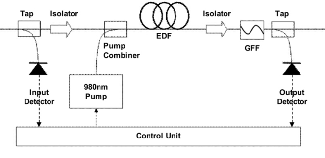
A long CATV system is always composed of head end, transmitter, receiver, CATV booster amplifier and optical splitter. When the system runs, the CATV signals are provided by the head end, and need to be split into several signals by the optical splitter to serve the users. When the signals pass through the optical splitter, the signal power would be in a very low level. Hence, the CATV EDFA optical amplifier should be deployed after the receiver to improve the signal power, and the users can finally receive quality signals.

CATV EDFA Optical Amplifier

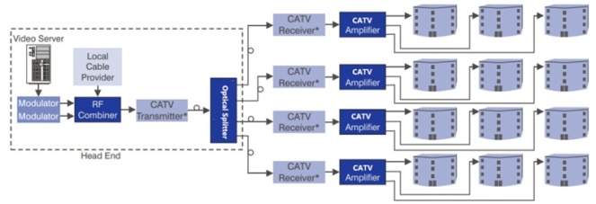
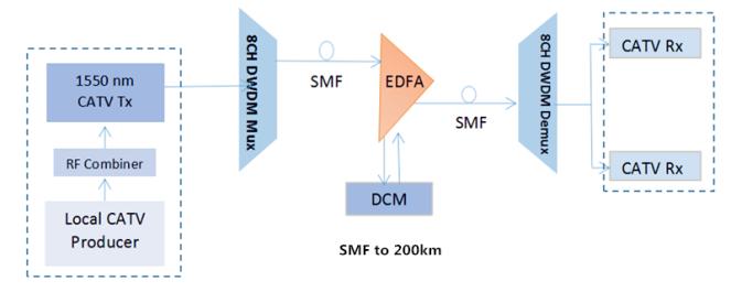
From the figure above, we can learn a simple point-to-multipoint CATV network design as mentioned above. The CATV signals are provided by the RF combiner and should be connected with four receivers by the optical splitter. In order to compensating the signal loss caused by the optical splitter, CATV EDFA optical amplifier is required before sending the weak signals to the users.

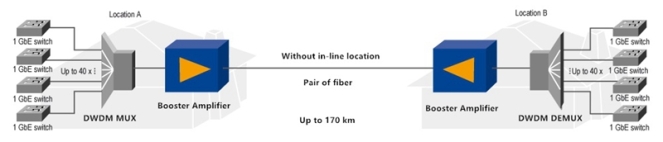
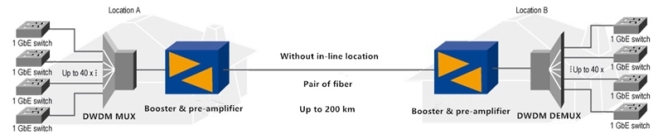
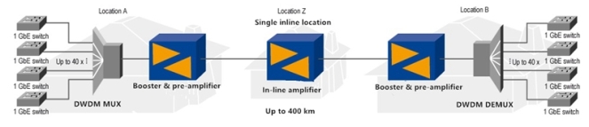
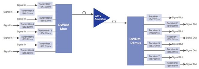
Except for this simple kind of CATV network using CATV EDFA optical amplifier, here also offers a complex CATV network, as designed in the figure below. In this CATV network, the CATV EDFA optical amplifier is deploy behind the 8 channel DWDM Mux Demux to amplify the signals while the 8 channel DWDM Mux Demux allows for higher capacity transmission. Hence, a long CATV network with big capacity can be achieved.

CATV EDFA Optical Amplifier with DWDM Mux

Conclusion

When deploying a long CATV system, we should pay attention to the loss caused by long transmission distance and CATV components. When the loss is very high, CATV EDFA optical amplifier would be an ideal device deployed in the long CATV system for improving the quality of CATV signals, so that the users can receive high speed and reliability of the services.

DWDM Network · Optical Amplifier

EDFA Amplifiers for Building Long-haul DWDM Networks

Clearly different from the traditional repeater, the EDFA amplifier doesn’t need to convert the optical signals into electrical ones, then make the electrical amplification and finally convert the amplified electrical signals into amplified optical signals again. It is an optical amplifier that can directly enhance the optical signals without making additional conversion. By using the EDFA optical amplifier, the attenuated signal power can be amplified into strong signal level to meet the requirement of the long-haul applications, especially the long-haul DWDM networks. To better understand the function of EDFA amplifier, the following will mainly study the working principle of EDFA amplifier works and illustrate how to use it to build the long DWDM network.

What’s the Working Principle of EDFA Amplifier?

From the figure below, we can learn the basic configuration of the EDFA amplifier, mainly composed of a length of EDF (erbium doped fiber), a pump laser with 980 nm or 1480 nm, a pump combiner and a simple WDM system. When the attenuated signals around 1550 nm pass through an EDFA amplifier, a pump laser will be generated. Then the DWDM signals and pump laser will be combined by the pump combiner. When they come into the EDF together, the wavelengths of signals and pump laser will be multiplexed and the interaction with the doping ions would enhance the signal power into high level. Thereby, a longer DWDM transmission can be reached.

EDFA Amplifier Configuration

How to Use EDFA Amplifier for Long DWDM network?

In a long DWDM network, the EDFA amplifier can be put in three different places with different aims. Firstly, we can put it in the transmitter side of the DWDM link to offer high input signal power, so that the DWDM fiber link can be extended. If the EDFA amplifier is deployed in this place, we can also call it EDFA optical booster amplifier. Secondly, we can also place the EDFA amplifier in the receiver side of the DWDM link as optical preamplifier, hence the output signal power can be boosted to meet the necessary receiver level. Finally, when the fiber loss in the transmission process is too high to support the long DWDM network, we can deploy the EDFA amplifier in any intermediate point along the long fiber link to compensate the fiber loss. And this time, we can call it EDFA optical in-line amplifier.

Analysis of Practical Long DWDM Cases with EDFA Amplifiers

Case One: in this case, EDFA optical booster amplifiers are deployed at both transmitter sides of the dual-way DWDM links. We can learn it from the figure below. Two 40 channel DWDM Mux Demux are deployed to multiplex 40 1G signals. Then the two integrated 40G signals from both sides are enhanced by the booster amplifier and can be transmitted up to 170 km over each single fiber.

EDFA Optical Booster Amplifier

Case Two: as shown in the following figure, except for the booster amplifiers, EDFA optical optical preamplifiers are also placed at both receiver sides of the dual-way DWDM links. By adding the optical preamplifiers to the CWDM link, the transmission distance is finally extended from 170 km to 200 km.

EDFA Optical Preamplifier

Case Three: it is highly noted from the following figure that the DWDM transmission distance can be up to 400 km. How to achieve this? Just putting the EDFA amplifiers in the three places mentioned above. As deployed in the figure, a pair of EDFA optical booster amplifiers, optical preamplifiers and optical in-line amplifiers are used for the 400km transmission.

EDFA Optical in-line Amplifier

Case Four: If the distance of 400 km still cannot meet our requirement, we can set up more repeater sites to place other optical in-line amplifiers. At present, using these three kinds of EDFA amplifiers already enables 100Gbps bandwidth for realizing up to 1000 km in a point-to-point connection, as shown in the figure below.

EDFA Amplifiers for 100G 1000km Tranmission

Conclusion

When designing a long-haul DWDM network for transmitting big data, EDFA amplifier is an ideal solution for current and future optical system which should be taken into consideration. It can be deployed at the transmitter side, the receiver side and any intermediate point along the DWDM long fiber link, as optical preamplifier, booster amplifier and in-line amplifier, for enhancing the signal power, thereby a long-haul transmission can be deployed.

DWDM Network · Optical Amplifier

How to Extend Your Network Transmission Distance?

To face the need for long-haul, high-capacity transmission, experts come up with several DWDM projects including DWDM Mux Demux, EDFA amplifier (erbium-doped fiber amplifier) and DCM module (dispersion compensation module) to expand network capacity and enhance the signal power, which can greatly extend the optical network reach. Do you have the need to deploy a longer fiber optical transmission link? If yes, you can just build a DWDM system with the DWDM projects mentioned above. This paper will introduce three solutions that utilize these DWDM components to extend the optical network transmission distance. Hope these DWDM solutions would be useful for you.

Using DWDM Mux Demux for Long Transmission up to 50 km

DWDM technology plays an important role in building long-haul transmission system, which enables multiple signals with different wavelengths to be transmitted through only one single fiber. To build a long system with DWDM technology, the DWDM Mux Demux is an indispensable component that features low insertion loss and polarization-dependent loss. By using the DWDM Mux Demux in your network, the signal transmission distance can be extended to up to 50 km. To better know the advantage of DWDM Mux Demux, here offers an example that uses two 8 channel DWDM Mux Demux for extending the optical fiber link.

8 channel DWDM Mux Demux for Long transmission

From the figure, we can learn that at the transmit side, eight kinds of signals from different fiber links are multiplexed into an integrated signal by the 8 channel DWDM Mux. Then the integrated signal is transmitted over the single mode fiber (SMF) and the maximum transmission distance can be up to 50 km. At the receiver side, the signal will be demultiplexed into individual signals with their original wavelengths by the 8 channel DWDM Demux and then transmitted to another eight different fiber links. Just by using the DWDM Mux Demux, a 50km long-haul transmission can be simply achieved.

Adding EDFA Amplifier for Transmission Longer Than 50 km

As we know, the longer the transmission distance is, the higher the fiber loss will be. Hence, except for the DWDM Mux Demux, you are suggested to add an EDFA amplifier to the long fiber link if the transmission distance is longer than 50 km. What’s the function of EDFA amplifier? It is mainly designed to amplify the signal power, which enables longer transmission. As shown in the following figure, you can learn that the only difference is the EDFA amplifier in the SMF, compared to the first solution.

EDFA and 8 channel DWDM Mux Demux for Long transmission

When the integrated signal multiplexed by the 8 channel DWDM Demux is transmitted over the SMF, it would become too weak in the transmission process to be transmitted. Then the EDFA amplifier should be placed there to boost the signal power, supporting the transmission longer than 50 km. Once the long transmission is realized, the signal will be also split by the 8 channel DWDM Demux, like the first solution. In short, DWDM Mux Demux and EDFA amplifier are highly suggested if you want to deploy a DWDM system longer than 50 km.

Adding DCM Module for Transmission up to 200 km

With the use of EDFA amplifier, the DWDM fiber link can be extended to 200 km. However, the signal quality is always unsatisfied due to the optical dispersion in long transmission, especially in CATV systems. To meet high requirements of the signal quality in these long transmission systems, an additional optical component, DCM module are needed in the long fiber link, as deployed in the figure below.

DCM, EDFA and 8 channel DWDM Mux Demux for Long transmission

From the figure, we can learn it is a long-haul point-to-multipoint CATV system. To extend the transmission distance, 8 channel DWDM Mux Demux, EDFA amplifier are used. Except for that, a DCM module is added to enhance the skew signal for ensuring the whole transmission quality. With the use of DCM module, the accumulated chromatic dispersion issue is solved, without dropping and regenerating the wavelengths on the long fiber link. Thereby, a high-performance 200km system can be reached.

Conclusion

DWDM projects including DWDM Mux Demux, EDFA amplifier and DCM module are key optical components to support long-haul transmission systems. If you want to deploy a long transmission system up to 50 km, then the DWDM Mux Demux is needed. For transmission longer than 50 km, both the DWDM Mux Demux and EDFA amplifier are required for boost the signal power. But once the transmission distance is about 200 km, you should additionally add the DCM module to enhance the signal quality.

Optical Amplifier

Whether to Use EDFA Amplifier in Long WDM System Or Not?

Currently, utilizing WDM technology to deploy the optical network has received widespread attentions, which enables higher capacity for data transmission. However, the technology is also limited by the transmission distance. When deploying a long WDM system, the signal power would still become weak due to the fiber loss. In order to address the issue, using EDFA amplifier to directly enhance the WDM signals would be a good choice for current and future optical network needs. The optical network combining WDM technology and EDFA module together can transmit multiple signals over the same fiber, at lengths up to a few hundred kilometers or even transoceanic distances. To better know how does EDFA amplifier work in the long WDM system, let’s learn the EDFA amplifier knowledge and analyze the performance of WDM system bonding with the EDFA module.

Introduction to EDFA Amplifier

EDFA amplifier, also referred to as erbium-doped fiber amplifier, is basically composed of a length of Erbium-doped fiber (EDF), a pump laser, and a WDM combiner. When it works, the pump laser with 980 nm or 1480 nm and the input signal around 1550 nm can be combined by the WDM combiner, then transmitted and multiplexed into the Erbium-doped fiber for signal amplification. The pump energy can be transmitted in the same direction as the signal (forward pumping), or the opposite direction to the signal (backward pumping), or both direction together. And the pump laser can also using 980 nm or 1480 nm, or both. Taking the cost, reliability and power consumption into account, the forward pumping configuration with 980nm pump laser EDFA amplifier is always the first choice to enhance the signals for a long WDM system.

Analysis of WDM Network Without EDFA Amplifier

Before analyzing WDM network deployed with EDFA amplifier, it is necessary to know the basic configuration of an original WDM network, as shown in the figure below. We can learn that four signals from different channels are combined by the optical combiner. And then, the integrated signals are transmitted through an optical fiber. Thirdly, the signals are split into two parts by the splitter. One part passes through the optical spectrum analyzer for analyzing signals, and the other one goes through the photo detector to be converted into electrical signal and then be observed by the electrical filter and scope. However, in the process, the signal power gets highly attenuated after being transmitting at long distance.

WDM System Without EDFA

Analysis of WDM Network Using EDFA Amplifier

By using the EDFA amplifier, we can easily overcome the attenuation of long WDM network. From the following figure, we can learn that EDFA amplifiers act as booster amplifier and pre-amplifier to enhance the signal, so that system will no longer suffer from losses or attenuation. Therefore, if you need to deploy a long WDM system, it is highly recommended to deploy the EDFA amplifiers in the system that features flat gain over a large dynamic gain range, low noise, high saturation output power and stable operation with excellent transient suppression. It is an undoubtedly ideal solution with reliable performance and relatively low cost to extend the WDM network transmission distance.

WDM System with EDFA

Conclusion

It is well know that the signal power would be greatly attenuated when the transmission distance is long enough. Hence, when deploying a long WDM network, it is definitely necessary to use the EDFA amplifier to enhance the signal strength, allowing for the long transmission distance. As a preferable option, the EDFA amplifier with very low noise is relatively insensitive to signal polarization and easy to realize signal amplification.

Optical Amplifier

EDFA vs Raman Optical Amplifier

Although the fiber loss limits the transmission distance, the need for longer fiber optical transmission link seems never ending. In the pursuit of progress, several kinds of optical amplifiers are published to enhance the signals. Hence, longer fiber optical transmission link with big capacity and fast transmission rate can be achieved. As the EDFA and Raman amplifiers are the two main options for optical signal amplification. which one should be used when designing long fiber optical network? What are the differences of the two optical amplifiers? Which one would perform better to achieve the long fiber optical link? And which one is more cost effective? Let’s talk about this topics.

What’s EDFA Amplifier?

EDFA (Erbium-doped Fiber Amplifier), firstly invented in 1987 for commercial use, is the most deployed optical amplifier in the DWDM system that uses the Erbium-doped fiber as optical amplification medium to directly enhance the signals. It enables instantaneous amplification for signals with multiple wavelengths, basically within two bands. One is the Conventional, or C-band, approximately from 1525 nm to 1565 nm, and the other is the Long, or L-band, approximately from 1570 nm to 1610 nm. Meanwhile, it has two commonly used pumping bands, 980 nm and 1480 nm. The 980nm band has a higher absorption cross-section usually used in low-noise application, while 1480nm band has a lower but broader absorption cross-section that is generally used for higher power amplifiers.

The following figure detailedly illustrates how the EDFA amplifier enhance the signals. When the EDFA amplifier works, it offers a pump laser with 980 nm or 1480 nm. Once the pump laser and the input signals pass through the coupler, they will be multiplexed over the Erbium-doped fiber. Through the interaction with the doping ions, the signal amplification can be finally achieved. This all-optical amplifier not only greatly lowers the cost but highly improves the efficiency for optical signal amplification. In short, the EDFA amplifier is a milestone in the history of fiber optics that can directly amplify signals with multiple wavelengths over one fiber, instead of optical-electrical-optical signal amplification.

EDFA Amplifier Principle

What’s Raman Amplifier?

As the limitations of EDFA amplifier working band and bandwidth became more and more obvious, Raman amplifier was put forward as an advanced optical amplifier that enhances the signals by stimulated Raman scattering. To meet the future-proof network needs, it can provide gain at any wavelength. At present, two kinds of Raman amplifiers are available on the market. One is lumped Raman amplifier that always uses the DCF (dispersion compensation fiber) or high nonlinear fiber as gain medium. Its gain fiber is relatively short, generally within 10 km. The other one is distributed Raman amplifier. Its gain medium is common fiber, which is much longer, generally dozens of kilometers.

When the Raman amplifier is working, the pump laser may be coupled into the transmission fiber in the same direction as the signal (co-directional pumping), in the opposite direction (contra-directional pumping) or in both directions. Then the signals and pump laser will be nonlinearly interacted within the optical fiber for signal amplification. In general, the contra-directional pumping is more common as the transfer of noise from the pump to the signal is reduced, as shown in the following figure.

Raman Amplifier Principle

EDFA vs Raman Optical Amplifier: Which One Wins?

After knowing the basic information of EDFA and Raman optical amplifiers, you must consider that the Raman amplifier performs better for two main reasons. Firstly, it has a wide band, while the band of EDFA is only from 1525 nm to 1565 nm and 1570 nm to 1610 nm. Secondly, it enables distributed amplification within the transmission fiber. As the transmission fiber is used as gain medium in the Raman amplifier, it can increase the length of spans between the amplifiers and regeneration sites. Except for the two advantages mentioned above, Raman amplifier can be also used to extend EDFA.

However, if the Raman amplifier is a better option, why there are still so many users choosing the EDFA amplifiers? Compared with Raman amplifier, EDFA amplifier also features many advantages, such as, low cost, high pump power utilization, high energy conversion efficiency, good gain stability and high gain with little cross-talk. Here offers a table that shows the differences between EDFA and Raman optical amplifiers for your reference.

Property EDFA Amplifier Raman Amplifier
Wavelength (nm) 1525-1565, 1570-1610 All Wavelengths
Gain (dB) > 40 > 25
Noise Figure (dB) 5 5
Pump Power (dBm) 25 > 30
Cost Factor Relatively Low Relatively High

Considering that both EDFA and Raman optical amplifiers have their own advantages, which one should be used for enhancing signals, EDFA amplifier, Raman amplifier or both? It strictly depends on the requirement of your fiber optical link. You should just take the characteristics of your fiber optical link like length, fiber type, attenuation, and channel count into account for network design. When the EDFA amplifier meets the need, you don’t need the Raman amplifier as the Raman amplifier will cost you more.

Original source: http://www.chinacablesbuy.com/edfa-vs-raman-optical-amplifier.html

Dispersion Compensation Module · DWDM Network · Optical Amplifier

How to Enhance the Optical Signals for a Long DWDM System?

As we know, the longer the optical transmission distance is, the weaker the optical signals will be. For a long DWDM system, this phenomenon easily causes transmission error or even failure. Under this case, what can we do for a smooth, long DWDM system? The answer is optical signal enhancement. Only by enhancing the optical signals, can the DWDM transmission distance be extended. In this post, we are going to learn two effective solutions, optical amplifier (OA) and dispersion compensation module (DCM) to enhance the signals, for making a smooth, long DWDM system.

Optical Amplifier Solution

We used to utilize repeater to enhance the signals in fiber optics, which should firstly convert the optical signals into an electrical one, amplify the electrical signals, and then convert the electrical signals into an optical one again. Finally, you can get the enhanced optical signals. However, this method of enhancing signals can not only cause more signal loss, but also add unwanted noises in the actual signal. Taking these issues into account, the optical amplifier is more recommendable.

An optical amplifier is a device that enables direct optical signal enhancement or amplification. Its working principle is not so complicated as that of the repeater, while its performance is much higher. From the following figure, we can learn that the original reach of the DWDM system is limited to 80 km due to the signal loss. But with the optical amplifier, the signals are enhanced and the reach can be extended to 160 km. It is really an ideal option to enhance the signals for a long DWDM system.

Optical Amplifier (OA)

At present, there are mainly three major kinds of optical amplifiers, Semiconductor Optical Amplifier (SOA), Doper Fiber Amplifier (DFA), and Raman Amplifier (RA).

Semiconductor Optical Amplifier: as its name implies, the semiconductor in a SOA is used to offer the gain medium. This kind of optical amplifier has a similar structure to the FP laser diode. However, it is designed with anti-reflection elements at the end face that can greatly reduce the end face reflection. Meanwhile, the SOA features small package and low cost that suits for most users to enhance the optical signals.

Doper Fiber Amplifier: in a DFA, the doped optical fiber acts as the gain medium for signal amplification. When the DFA works, the signal to be amplified and a pump laser are multiplexed into the doped fiber. And then the signal is amplified through interaction with the doping ions. The most common DFA is the Erbium Doped Fiber Amplifier (EDFA). Its gain medium is a optical fiber doped with trivalent erbium ions that always enhances the signals near 1550nm wavelength. Undoubtedly, the EDFA is a great choice to enhance the optical signals.

Raman Amplifier: different from the SOA and DFA, the signal in a RA is amplified through the nonlinear interaction between the signal and a pump laser within an optical fiber. In details, two kinds, distributed and lumped Raman amplifier (DRA and LRA) are available on the market. The distributed one multiplexes the pump wavelength with signal wavelength through the transmission fiber to enhance the signals, while the amplification of the lumped one is provided by a dedicated, shorter length of fiber.

Dispersion Compensation Solution

Apart from signal amplification, we can also use dispersion compensation to enhance the optical signals. Once the dispersion occurs, the signal will be tended to skew due to the different frequencies, which has a negative effect on the quality of signal transmission. At that moment, we use the dispersion compensating module to enhance the skew signal, for achieving a longer transmission distance. As shown in the figure below, the DWDM system is extended to longer than 80 km with the use of 80km passive dispersion compensation module.

Dispersion Compensating Module (DCM)

The dispersion compensation module is an important component for a long fiber optical link. It typically connects to the mid-stage of an OA like EDFA, in the long haul transmission system. Except for the 80km DCM mentioned above, FS.COM also provides other DCM modules that allow long transmission distance extension. The compensation distances can range from 10km to 140 km, as shown in the following table.

Module Type Description
FMT10-DCM 10KM Passive Dispersion Compensation Module, Plug-in Type, LC/UPC
FMT20-DCM 20KM Passive Dispersion Compensation Module, Plug-in Type, LC/UPC
FMT40-DCM 40KM Passive Dispersion Compensation Module, Plug-in Type, LC/UPC
FMT60-DCM 60KM Passive Dispersion Compensation Module, Plug-in Type, LC/UPC
FMT80-DCM 80KM Passive Dispersion Compensation Module, Plug-in Type, LC/UPC
FMT100-DCM 100KM Passive Dispersion Compensation Module, Plug-in Type, LC/UPC
FMT140-DCM 140KM Passive Dispersion Compensation Module, Plug-in Type, LC/UPC

Conclusion

The optical amplifier has the ability to directly boost the weak signal, while the dispersion compensation module can reshape the deformed signal and offer a long compensation distance. Considering that the signal strength would become weak as the transmission distance increases, using the optical amplifier and dispersion compensation module to enhance the signals is very necessary when building a long DWDM system.

Original source: http://www.chinacablesbuy.com/enhance-optical-signals-long-dwdm-system.html