Fiber Optic Patch Cable

Properly Terminate Fiber Optic Cables for a Smooth Connection

In the optical network deployment, fiber optic termination should be an unavoidable and vitally important procedure that enables fiber cross connection and light wave signal distribution. Only when the fiber optic cables in the network are terminated properly can they be protected from dirt or damage so as to achieve a smooth and steady network. Meanwhile, proper fiber optic termination can efficiently avoid the excessive loss of light when the network runs, which strengthens the smooth connection. But how to properly terminate fiber optic cables to ensure a smooth connection? Let’s talk about this topic and find the most suitable method to terminate fiber optic cables for your network.

Proper Methods for Fiber Optic Termination

There are two methods for terminating fiber optic cables, using connectors and splicing, each of which allows for a smooth connection with low light loss and back reflection in a proper manner. We can learn these two methods in the following figure. The method of using connectors to terminate fiber optic cables is shown in the top right corner that is able to mate two fibers for a temporary joint, while the other method is splicing which has the ability to create a permanent joint between the two fibers. As for the step-by-step instructions of these two methods, it will be introduced detailedly in the following text.

fiber optic termination methods

Using Connectors to Terminate Fiber Optic Cables

You may often hear about the descriptions like LC to LC patch cord, LC to SC patch cord and LC to FC patch cord when choosing fiber patch cords to deploy your network. Do you understand what do the words “LC” “SC” and ”FC” mean? In fact, they stand for three kinds of connectors that are to terminate the ends of fiber optic cables, with the aim of connecting and disconnecting two fibers for many times without affecting the optical performance of the fiber circuit. To get a smooth fiber circuit, the following will illustrate how to use the connectors to properly terminate fiber optic cables.

  • Take out the fiber optic cable that you want to terminate and prepare a fiber cleaver for the termination.

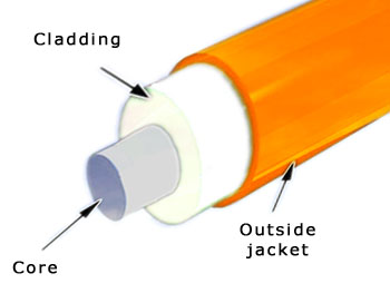
  • Strip away the outer jacket, buffer and cladding of the fiber optic cable and cut away the excess aramid yarn.

  • Lightly score the fiber by pressing the fiber cleaver. Don’t use the cleaver more than once to score the fiber, so that the fiber will not be broken by unexpected, additional notch.

  • Along the score, bend the fiber and the tongue of the cleaver together to break the fiber.

  • Use the scale on the cleaver for measuring the bare fiber to ensure that it is long enough, so that it can reach the fiber inside the connector and make the termination work finally.

  • Utilize alcohol wipes with at least 90% isopropyl alcohol content and lint-free material to clean the fiber.

  • Carefully insert the bare fiber into the connector and crimp the connector onto the buffer.

Notices: Please check and confirm the right types of connectors and their polishing styles before making the termination to avoid non-corresponding installation. Moreover, test periodically during the installation, rather than testing them all after the job is completed to eliminate the possibility of repeating the same errors throughout the installation.

Splicing to Terminate Fiber Optic Cables

When the fiber cable is too long or there are various fiber cables that needs to be mixed, the splicing is strongly recommended to do the fiber optic termination. For instance, splicing a 48-fiber cable and six 8-fiber cables together. Meanwhile, if a buried finer cable is accidentally severed, you are also suggested to use the splicing method to restore the fiber optic cable. The following will introduce the procedures of fusion splicing which may be useful for you to make a proper fiber optic termination.

  • Prepare the two fiber ends that need to be spliced together.

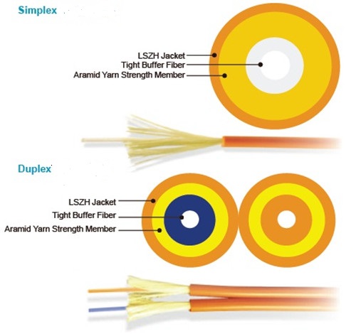
  • Strip the protective coating, jackets, tubes, strength members, etc, and only leave the bare fiber showing.

  • Clean the fiber cables and use score-and-break method to score the fibers, for the sake of proper splicing.

  • Properly align the cleaved end-faces of the two fibers, and then utilize an electrical arc to melt them. Hence, the two fiber ends can be permanently welded together.

  • Finally use the heat shrink tubing, silicone gel and mechanical crimp protector to protect the splice from outside elements and breakage.

Conclusion

From the mentioned above information, we can easily acquire two proper methods for fiber optic termination, using connectors and splicing, both of which are the useful and effective solutions to achieve smooth connections. Using these two methods to terminate fiber optic cables can protect the fibers from being damaged, avoid the excessive loss of light and keep a stable performance for your network.

Fiber Optic Patch Cable

Traceable Fiber Patch Cable Overview

What Is Traceable Fiber Patch Cable?

Traceable fiber patch cable is clearly different from original fiber patch cable that features the exceptionally bright, integrated LED light at each end of the fiber cable, aiming at satisfying the ever-growing demand to quickly and easily identify and trace network connections in today’s high-density and mission-critical infrastructure environments.

trace-patch-cable

As shown in the figure above, the flashing LED light at each end of traceable fiber patch cable is to easily trace individual patch cable from one side to another without pulling or affecting the whole patch cables. By using this kind of fiber patch cable, your network can be fast and simply maintained, while the erroneous connections of network can be also easily found and quickly resolved. In short, traceable fiber patch cable is an ideal solution that allows for easy port identification.

How Does Traceable Fiber Patch Cable Work?

The working process of traceable fiber patch cable is very easy to handle. Just press the activation button on the low-profile plug, the LED lights will flash immediately on both ends of the patch cable for easy identification of where the patch cable is connected. To get a visual understanding of the working process, the following figure shows the detailed information of how to use traceable fiber patch cable for tracing network connection.

traceable-fiber-patch-cable

Traceable fiber patch cable is capable of eliminating the possibility of accidentally unplugging or connecting wrong patch cable, which is highly recommended in high-density environments. For instance, if there is cable congestion in your network and it is very difficult to find the opposite end of one cable, the traceable fiber patch cable should be very suitable for you to address the problem.

Features and Benefits

Traceable fiber patch cable is designed with distinctive features and benefits, which enables quick and accurate port identification for high-density and high congestion network. It is very different from other fiber patch cables and would be an exceptional alternative to others for its distinctive advantages in the following aspects.

First and foremost, the LED indicators at both ends of the fiber cable offer an visual indication for easy port identification, superior to other fiber patch cables. When the LED tool applies power to the fiber patch cable, it is able to identify the the two ends of the cable, eliminating and avoiding connection mistakes. Secondly, the assemblies are available in single-mode bend insensitive fiber (BIF) and multimode OM3 and OM4 fiber types, both of which have the ability to reduce insertion loss when through high density equipment. Thirdly, all of the assemblies conform with TIA/EIA and IEC intermateability standards, and RoHS compliant. With this design, it greatly saves installation, maintenance and trouble shooting time as a time and cost efficient choice.

Traceable Patch Cables Selection Guides

The types of traceable patch cable are similar to the original fiber patch cable, including single-mode and multimode traceable patch cable, simplex and duplex traceable patch cable and so on. Multimode traceable patch cable is designed for short distance transmission, while single-mode traceable patch cable is more suitable for transmitting signals with much longer distance. If high-speed transmission is required, simplex traceable patch cable must be a good choice. But if the reliability of transmission is quite important, the duplex traceable patch cable is much more recommended.

Conclusion

Traceable fiber patch cable can simplify and accelerate the deployment of high density network with the advantage of easy port identification. At present, there are several types of traceable patch cables that can be chosen for your network according to your network need. Except the common types mentioned above, it is also available in various connectors used for different applications, which is the same as original fiber patch cables like LC SC fiber patch cable and SC ST fiber patch cable. If these types can not meet your needs, you can make custom fiber patch cables which are more suitable for your network to quickly and easily trace connection.

Fiber Optic Patch Cable

MPO/MTP Solution for High-Density Data Centers

With the rapid development and prevalence of cloud computing and big data, the requirements for transmission speed and data capacity become much higher than ever before, which makes 40/100G Ethernet be an inevitable trend for data center cabling system. However, as science and technology develop day by day, new questions are always following soon and waiting for the right solutions. For the coming and progress of 40/100G Ethernet network, the traditional LC cabling is too complicated to meet the demands for high density in data centers. Thus, making the traditional LC cabling less complicated or designing a brand new kind of cabling to replace the previous one becomes an imminent issue.

How to solve the issue so that the time and space spent on cable installation would not be wasted? MPO/MTP cabling solution turns out to be the right method for high-density, easy plug and play connection in complicated cabling infrastructure.

What’s MPO/MTP?

MPO/MTP is a technology deployed for multi-fiber applications, which aims at pulling just one single cable with multiple fibers. The word MPO stands for “Multiple-Fiber Push-On/Pull-off”. Through MPO/MTP technology, you can replace 12 or 24 LC connectors with only one MPO/MTP connector. In other words, you only need to patch one cable with multiple fibers, instead of patching 12 or 24 separate fiber cables.

Generally, MPO/MTP technology is a high-density, high-performance solution, widely used for 40/100G Ethernet network as well as fast installation of enterprise data center. With the advantage of MPO/MTP fiber systems, a much higher bandwidth transmission in data communication is no longer a dream.

MPO/MTP Fiber Optic Jumper Cable

MTP/MPO fiber optic jumper cable consists of MTP/MPO cable and MTP/MPO connectors, which is designed for the reliable and quick operations in data centers. With its advantages of less space and scalability improvement, significant space and cost savings are provided to user. What should be noted is that MTP cable is upgrade version of the former MPO, with better optical and mechanical performance. As for the connectors, both MTP and MPO connectors are multi fiber connectors, each of which has many fiber optic channels. Since MPO/MTP connectors are the up-and-coming standard optical interface for 40/100G Ethernet network, there is no doubt that MPO/MTP fiber optic jumper cable will eventually flood the data center. After all, the high fiber count in one connector creates endless possibilities.

photo1.png

Advantages of MPO/MTP Products

Compared with traditional fiber products, there are many improvements in MPO/MTP Products, such as, faster and easier installation, lower cost and higher density with less space. The following will introduce the detailed information for MPO/MTP products’ advantages.

As we know, in contrast to traditional fiber cabling, MPO/MTP cabling is much easier and faster. It is estimated that the installation time of MPO/MTP cabling can be reduced by up to 75% for MPO/MTP products’ simple push-pull latching mechanism. The installation method of MPO/MTP products is just pulling and plugging, which is designed to easy and intuitive insertion and removal. Hence, all unpredictable field termination troubles can be eliminated, while the installation time involving a costly high-qualified workforce can be reduced to a minimum.

High density is another feature of MPO/MTP products. For their multi-fiber structure, there are 12/24 fibers in only one cable running at the same time, providing 12/24 times the density, which facilitates high density communication. Beside, most MPO/MTP products belong to modular solutions, which could be a good choice to ease future expansion and for quick and easy system reconfiguration.

Conclusion

With the improvement of network technology, 40/100G Ethernet seems to be a prevalent trend. To meet the growing demands of fiber optic market, MPO/MTP products are developed and largely used in a really fast manner, dramatically providing the ideal solution for high density cabling data center.

Fiber Optic Patch Cable

Simplex vs. Duplex Fiber Jumpers

Introduction

Instead of copper jumper, fiber jumper plays an important role in telecommunication infrastructures, with a great improvement in the properties of repeatability, confidentiality, transmission speed and transmission capacity to realize the data transmission with low loss. For its largely use, there are a wide range of fiber jumpers available on the market developed for different aims, such as, single mode fiber jumpers, duplex fiber jumpers, ST to LC Fiber Jumper, etc. Different fiber jumpers vary from the color of fiber jumpers to their applications, which can be classified by different standard. In this paper, it will mainly introduce the differences between simplex and duplex fiber jumpers that are classified according to different cable quantities.

Simplex VS. Duplex Fiber Jumpers

Many types of fiber jumpers have been developed at different times, for different purposes. On the basis of cable quantities, fiber jumpers can be divided into two types, simplex fiber jumper and duplex fiber jumper. The two fiber jumpers are completely distinct from structure to working principle, which can be used for different applications. From the following figure, you can learn that the left fiber jumper is a kind of simplex fiber jumper and the right one belongs to duplex fiber jumper.

photo2

Structure Comparison

Simplex fiber jumper is tight-buffered and jacketed that has only one fiber cable with one optical core and cladding. The signal will be transmitted over the one fiber cable. In contrast to simplex fiber jumper, duplex fiber jumper is also tight-buffered and jacketed, but has two separate simplex fiber cables working at the same time. The two separate simplex cables have their own jackets linked together by a kind of material. More detailed information about structural differences for simplex and duplex fiber jumpers is shown in the figure below.

photo1.jpg

Working Principle Comparison

As for duplex fiber jumper, it works simply, transmitting the signals by two separate simplex cables from opposite sides. When one cable is sending the signal from one side, another cable can receive the signal and send another signal from the opposite side simultaneously. The speed of transmitting signals over duplex fiber jumper is slower than over simplex fiber jumper, while the reliability of transmitting signals by duplex fiber jumper is higher. For the sake of high reliability of sending and receiving signals, the duplex fiber jumper must be highly recommended.

Completely different from duplex fiber jumper, simplex fiber jumper has only one fiber cable, which means the signal transmission through simplex fiber jumper can be only running in one direction at a time. That’s to say, when the signal is transmitted from one side of the fiber jumper, the other side cannot sending another signal until receiving the previous signal. It is really inconvenient and cannot meet the requirement of the market.

As time goes on, a new type of simplex fiber jumper is developed, designed for transmitting the duplex signals respectively over one fiber cable by using two optical signals with different wavelengths. Hence, the data can be transmit in two directions at the same time. In simple words, when one signal is sending from one side of the fiber cable, another signal with a different wavelength can be also sending from the other side at the same time, without mutual interference. Compared to the duplex fiber jumper, the simplex fiber jumper has a great improvement in the high speed of sending and receiving the signals, which also saves the optical fiber resource.

Conclusion

Did you get the detailed differences between simplex fiber jumper and duplex fiber jumper from this paper? If high reliability is required, you are suggested to choose duplex fiber jumper for your network; for the sake of transmission speed, simplex fiber jumper must be a good choice. Besides, except for simplex and duplex fiber jumper, fiber optic patch cord manufacturer has manufactured many other types of fiber jumpers to meet the market needs since fiber jumper has become an indispensable device in today’s optical network. You should master the features and applications of each fiber jumper, so that you can easily choose the right one for your own network.

Fiber Optic Patch Cable

Multimode Patch Cable Solution

Great Challenge with Existing Multimode Patch Cables

As we know, single mode fiber cables are suitable for 10 Gigabit Ethernet due to its advantages of high speed and capacity. For instance, LC to LC single mode fiber patch cable and LC to SC single mode fiber patch cable, work with high-performance in 10 Gigabit Ethernet. However, taking the manufacturing cost of single-mode patch cable into consideration, it still can’t be largely used in 10 Gigabit Ethernet at present. How to lower the cost without loss of transmission quality? Is there another patch cable with low cost that can substitute for single-mode patch cable, so that it can be deployed in a cost-effective manner in today’s fiber optic market? In order to solve this, researchers attempt to improve the performance of multimode patch cable to support 10 Gigabit Ethernet.

Emergency of OM3 Patch Cable

With the increasing improvement of network, 10 Gigabit Ethernet seems to have been inevitable, which also brings a big challenge to multimode patch cable. Accordingly, enhancing the performance of multimode patch cable has become an inexorable trend.

It is well known that traditional multimode patch cables are used to be applied in 100 Megabit Ethernet and 1 Gigabit Ethernet applications. Is it also able to support 10 Gigabit Ethernet? With the birth of OM3 patch cable, the answer is yes. (The word “OM” stands for optical multimode.) To fulfill the requirement of fiber optical market, the advanced multimode patch cable, OM3 patch cable is developed which can be also applied in 10 Gigabit Ethernet and transmit the signals at lengths up to 300 meters. As for the cost, it is just a little bit more expensive than original multimode patch cable that meets our need. The patch cables in the following figure are the OM3 patch cables, which are largely used in high-speed communication nowadays.

photo1.png

Superior OM4 Patch Cable

Apart from OM3 patch cable, there is a more superior multimode patch cable, OM4 patch cable which has come to fiber optic market. It is designed to support 10 Gigabit Ethernet at lengths up to 550 meters, which also supports 40 Gigabit Ethernet and 100 Gigabit Ethernet at lengths up to 150 meters. With the development of OM4 patch cable, the 40 Gigabit Ethernet and 100 Gigabit Ethernet could be available easily with a cost-effective method, thereby big preference is provided for the users. The patch cable in following figure is a kind of the OM4 patch cable for your reference.

photo2

Differences Between OM1, OM2 , OM3 and OM4

Compared with the OM1 and OM2 patch cables, OM3 and OM4 patch cables have been improved in many aspects. As for the diameter, both of their cladding diameters are 125 µm, but their core diameters are different. In details, the core diameters of OM1 patch cable is 62.5 µm, while the core diameters of OM2, OM3 and OM4 patch cables are smaller, 50 µm. As for the jacket colors, OM1 and OM2 patch cables are orange, but OM3 and OM4 are aqua. As for the optical source, traditional LED is used in OM1 and OM2 patch cables, as VCSEL is used in OM3 and OM4 patch cables with a lower loss. Besides, the bandwidth of the patch cables is designed to be wider and wider to face the high-speed network. From the following figure, we can know exactly the details of four multimode patch cables.

photo3

Each multimode patch cable is suitable for different applications. Generally, OM1 patch cable is always used to support 100 Megabit Ethernet applications at lengths up to 2000 meters; while OM2 patch cable is more commonly applied in 1 Gigabit Ethernet within a 550-meters transmission distance. As for OM3 patch cable, it is designed to support the applications of 10 Gigabit Ethernet, and its transmission distance can be 300 meters. As for OM4 patch cable, it is more superior that can support 40 Gigabit Ethernet and 100 Gigabit Ethernet and transmit signals at lengths up to 150 meters.

Conclusion

The development of science and technology will never stop, so does the improvement of multimode patch cable. With the unremittingly increasing requirement of today’s optical network, the multimode fiber optic cables would be developed to support 100 Gigabit Ethernet with longer transmission distance, even support 120 Gigabit Ethernet.

Fiber Optic Patch Cable

Comparison of Multimode Patch Cable and Single-mode Patch Cable

Fiber optic patch cables are also referred to as fiber optic patch cords or fiber optic jumper cables, which are designed to connect the optical transmitter, receiver and terminal box in a simple way. With the greater advantages, the fiber optic patch cables become an inevitable choice to set up large-scale network, instead of copper cables. To meet the requirement of fiber optics market, the types of fiber optic patch cables are being more and more diversifying, which can be classified by fiber cable mode, fiber cable structure, connector types, etc.

When selecting the fiber optic patch cables, you’ll find many types of fiber optic patch cables in your list and you may feel a little confused about the selection. In this article, it will mainly introduce the differences between single-mode patch cable and multimode patch cable, which will help you have a good knowledge of this classification.

Structure Difference

In general, the fiber optic patch cable is composed of fiber optic cable and connectors in the view of the external structure. As for the internal structure, it has one transparent glass core with the property of high refractive index in the center of fiber optic patch cable, which makes optical signal transmitted as long as possible with low loss. Meanwhile, the core is covered by a protective cladding with the property of low refractive index, which strengthens the function of low signal loss. Besides, the fiber optic patch cable has a thick jacket outside to protect its core and cladding from the damage of external environment.

However, in addition to the similarities, there is a true structural difference between single-mode patch cable and multimode patch cable. Detailedly, the core diameter of the multimode patch cable is always 50 μm or 62.5 μm, while the core diameter of the single-mode patch cable is much smaller, 9μm. From the following picture, we can know exactly what the core diameter difference is between single-mode patch cable and multimode patch cable.

photo1

Color Difference

Fiber optic patch cables are always differently colored, such as, yellow, orange. Is there any classification according to distinct color? In principle, the color of the single-mode patch cable is yellow, as the multimode patch cable is orange, aqua or light blue. That’s to say, yellow optic patch cable would be a single-mode patch cable, and the aqua fiber patch cable is usually a multimode patch cable. The following figure provides the color difference between single-mode patch cable and multimode patch cable for your reference.

photo2

Application Difference

For its small core diameter, the single-mode patch cable can only carry the single optical signal in the same mode with different frequencies, which has little modal dispersion in the signal transmission. Meanwhile, its light source is provided by laser, which means that the signal power in single-mode patch cable is very strong. Therefore, the single-mode patch cable is commonly used in the applications for long distance transmission. What should be noted is that, due to its advantages of wide transmission band, big capacity and high speed, it is much more expensive than the multimode patch cable.

As for the multimode patch cable, it is clearly different from the single-mode one. It can carry more than one light signals in the different modes, which requires a much longer core diameter. Under this condition, it seriously causes the disadvantage of large dispersion. The longer the distance the signal is transmitted through multimode patch cable, the larger the dispersion is. Besides, its light source is provided by LEDs and the signal power in multimode patch cable is not so strong as in single-mode patch cable accordingly. Hence, the multimode patch cable is designed for short distance transmission with lower cost.

photo3

Conclusion

It can be concluded from this article that different fiber patch cables are designed for specific aims. If you want the high-speed and long-distance transmission, you are suggested to choose the single-mode patch cable; if low cost and short-distance transmission is demanded, the multimode patch cable must meet your needs. Just choose the suitable one for your network.

Fiber Optic Patch Cable

Introduction of Multimode Fiber Optic Cable

The multimode fiber optic cable is commonly applied in short distance communication. It has the properties of low insertion loss, good repeatability, high return loss and excellent temperature stability, which is largely used nowadays. However, it has a serious disadvantage of large dispersion. The longer the distance the signal transmits, the larger the dispersion is. Therefore, the multimode fiber optic cable is suggested to be used in the applications for short distance transmission.

Comparison With Single-mode Fiber Optic Cable

Clearly different from the single-mode fiber optic cable, the multimode fiber optic cable can carry more than one light signal in the different modes, which requires a much longer diameter of its core. In general, the core diameter of multimode fiber optic cable is about 50-100 µm. However, because of its large dispersion, the multimode fiber optic cable is only suitable for short communication.

photo1

Figure 1. Structure of single-mode fiber optic cable and multimode fiber optic cable

Furthermore, the multimode fiber optic cable is only suitable in 1 Gigabit Ethernet., while the single-mode fiber optic cable is able to transmit signals in 10 Gigabit Ethernet. But considering the manufacturing cost of single-mode fiber optic cable, it can’t be largely used in 10 Gigabit Ethernet. Therefore, improving the performance of multimode fiber optic cable to support 10 Gigabit Ethernet has become an inexorable trend.

Development of Multimode Fiber Optic Cable

With the improvement of network applications, 10 Gigabit Ethernet seems to have been inevitable. To meet the requirement of fiber optic market, the advanced multimode fiber optic cables are developed which can be also applied in 10 Gigabit Ethernet. As for the cost, the advanced multimode fiber optic cable is a little bit more expensive than original multimode fiber optic cable.

At present, there are four types of multimode fiber optic cables in fiber optic market, OM1, OM2, OM3 and OM4. The word “OM” is the acronym of optical multimode.

As for the four types of multimode fiber optic cables, they have different properties and can be used in different applications. In general, OM1 is always used to support 100 Megabit Ethernet applications; while OM2 is more commonly applied in 1 Gigabit Ethernet. As for OM3, it is designed to support the applications of 10 Gigabit Ethernet. And OM4 is more superior which can support 100 Gigabit Ethernet.

Basic Differences Between OM1, OM2, OM3 and OM4

The multimode fibers can be distinguished by their core and cladding diameters. All cladding diameters of the four multimode fibers are 125 µm. But their core diameters are different. The core diameter of OM1 is 62.5 µm, while the core diameters of OM2, OM3 and OM4 are 50 µm.

OM1 and OM2 have the orange jackets and their optical source is LED. Different from OM1 and OM2, OM3 and OM4 have aqua jackets and their optical source is 850nm VCSEL.

They can also be described by different bandwidth. OM1 has 200 MHz*km bandwidth, and OM2 has 500 MHz*km bandwidth. As for OM3, it provides sufficient bandwidth to support 10 Gigabit Ethernet, which is 2000MHz*km. To be used in 100 Gigabit Ethernet, the design of OM4 maximizes the bandwidth, so that OM4 has 4700MHz*km bandwidth, much wider than previous types.

photo3

Figure 2. Basic differences between OM1,OM2,OM3 and OM4

OM1, OM2, OM3 and OM4 in Different Applications

All of the four types of multimode fiber optic cables can support 100 Megabit Ethernet for communication at lengths up to 2000 meters.

In 1 Gigabit Ethernet, the transmission distances of OM1 can be 275 meters; the transmission distances of OM2 and OM3 are 550 meters at most; and the transmission distances of OM4 is the longest, 1000 meters.

In 10 Gigabit Ethernet, OM1 can only transmit signals at lengths up to 33 meters; OM2 has the performance of 82 meters transmission distance; OM3 can transmit longer, 300 meters; and OM4 can transmit longest, 550 meters.

In order to support 40 Gigabit Ethernet and 100 Gigabit Ethernet, OM3 and OM4 have been developed. It should be noted that OM3 can be used in both 40 Gigabit Ethernet and 100 Gigabit Ethernet with 100 meters transmission distance. As for OM4, it is a further improvement that can support both 40 Gigabit Ethernet and 100 Gigabit Ethernet at lengths up to 150 meters.

photo2

Figure 3. OM1,OM2,OM3 and OM4 in different applications

In short, OM1 is always used for 100 Megabit Ethernet applications which can transmit 2000 meters with the lowest cost; while OM2 is more commonly used in 1 Gigabit Ethernet. These two multimode fiber optic cables are not very suitable for high-speed communication nowadays. Therefore, to fulfill the need of the fast network development, advanced multimode fiber optic cables OM3 and OM4 are invented. OM3 is designed to support the applications of 10 Gigabit Ethernet, and OM4 is more superior that can support 100 Gigabit Ethernet at lengths up to 150 meters.

Conclusion

With the fast development of network, the multimode fiber optic cables would be improved to support 40 Gigabit Ethernet and 100 Gigabit Ethernet with longer transmission distance, which is the future development prospect in fiber optics market.

Fiber Optic Patch Cable

Introduction of Commonly Used Fiber Optic Patch Cables

Introduction of Fiber Optic Patch Cable

The fiber optic patch cable is a jumper wire invented to connect the optical transceiver, receiver and terminal box, which facilitates the data transmission with a simple and low-loss way. Compared to the traditional copper cable, fiber optic cable has a great improvement in the property of repeatability, confidentiality, transmission speed and transmission capacity to realize the data transmission with low loss. Therefore, fiber optic patch cable is an inevitable choice to set up large-scale and long-distance network, instead of copper cable.

Structure of Fiber Optic Patch Cable

In general, the fiber optic patch cable is composed of fiber optic cable and connectors in the view of its external structure.

fiber-patch-cords.png

Figure.1 The external fiber optic patch cable.

As for its internal structure, there is a transparent glass core with the property of high refractive index in the center of fiber optic patch cable, which makes light signal transmitted as long as possible with low loss. The diameter of the core in an ordinary fiber optic patch cable is about 125µm, as wide as a single hair of human. With the development of fiber optic patch cable, the diameter of the core is smaller and smaller. For instance, the diameter of the core in the single-mode cable is only 9 µm, much smaller than ordinary cable’s. Furthermore, the core is covered by a protective cladding with the property of low refractive index, which strengthens the function of low signal loss. Besides, the fiber optic patch cable has a thick jacket outside to protect its core and cladding from the damage of external environment.

photo3

Figure.2 The internal structure of fiber optic patch cable

Commonly Used Fiber Optic Patch Cables

When selecting the fiber optic patch cables to use, you’ll find many types of fiber optic patch cables in your list and you may feel a little confused about the selection. Here are the detailed characteristics of some commonly used fiber optic patch cables for your reference which may meet your need.

Fiber Optic Patch Cables Classified by Transmission Medium

On the basis of the different transmission medium, the fiber optic patch cables can be divided into two types, single-mode fiber cable and multimode fiber cable.

The Characteristics of Single-mode Fiber Cable and its Application

The single-mode fiber cable can only carry a single light signal in the same mode with different frequencies, which has little modal dispersion in the signal transmission. As a result, it is designed for long distance transmission. For its advantages of wide transmission band, big capacity, high speed and long transmission distance, is it also more expensive than the multimode fiber cable.

The Characteristics of Multimode Fiber Cable and its Application

Clearly different from the single-mode fiber cable, the multimode fiber cable can carry more than one light signals in the different modes, which required a much longer diameter of its core. However, it causes a serious disadvantage of large dispersion. The longer the distance the signal is transmitted through multimode fiber fiber cable, the larger the dispersion is. Therefore, the multimode fiber cable is commonly used in the applications for short distance transmission.

photo2

Figure.3 The different signal transmissions between single-mode fiber cable and multimode fiber cable

Fiber Optic Patch Cables Classified by Cable Quantities

According to the different cable quantities, there are two types of fiber patch cables commonly used nowadays, simplex fiber patch cable and duplex fiber patch cable.

The Characteristics of Simplex Fiber Patch Cable and its Application

The simplex fiber patch cable has only one fiber optic core and cladding. For the only one fiber, the signal transmission through simplex fiber patch cable can be running in one direction at a time. However, as time goes on, the new simplex fiber patch cable is developed which designed for transmitting the duplex signals respectively by using two light signals with different wavelengths. As a result, the data can be transmit in two directions at the same time. Compared to the duplex fiber patch cable, the simplex fiber patch cable has a great improvement in the high speed of sending and receiving the signals, which also saves the optical fiber resource.

fiber-optic-patch-cord-sc-pc-sm-simplex-3-0mm-1m

Figure.4 The simplex fiber patch cable

The Characteristics of Duplex Fiber Patch Cable and its Application

The duplex fiber patch cable is also tight-buffered and jacketed like the simplex fiber patch cable. But there are two separate simplex cables with their own jackets linked together by a kind of material. It works simply, carrying the signals by two separate simplex cables. When the one cable is sending the signal in one direction, another cable can receive the signal and send another signal in the other direction simultaneously. The reliability of transmitting signals by duplex fiber patch cables is higher than transmitting by simplex cables, but the speed of transmitting signals by duplex fiber patch cables is slower. For the sake of high reliability of sending and receiving signals, the duplex fiber patch cable must be a good choice.

photo1

Figure.5 The duplex fiber patch cable

Conclusion

To meet the requirement of fiber optic cable market, the types of fiber optic cable is being more and more diversifying. It can be concluded from this article that the different fiber cables are designed for specific aims. In short, the single-mode fiber cable is suitable for long distance transmission, while the multimode fiber cable is commonly used in the applications for short distance transmission. If you want the high-speed transmission, you are suggested to choose the simplex fiber patch cable; if the reliability of transmitting signals is required, the duplex fiber patch cable must meet the need.